Y4 Coaxial Multirotor Configuration
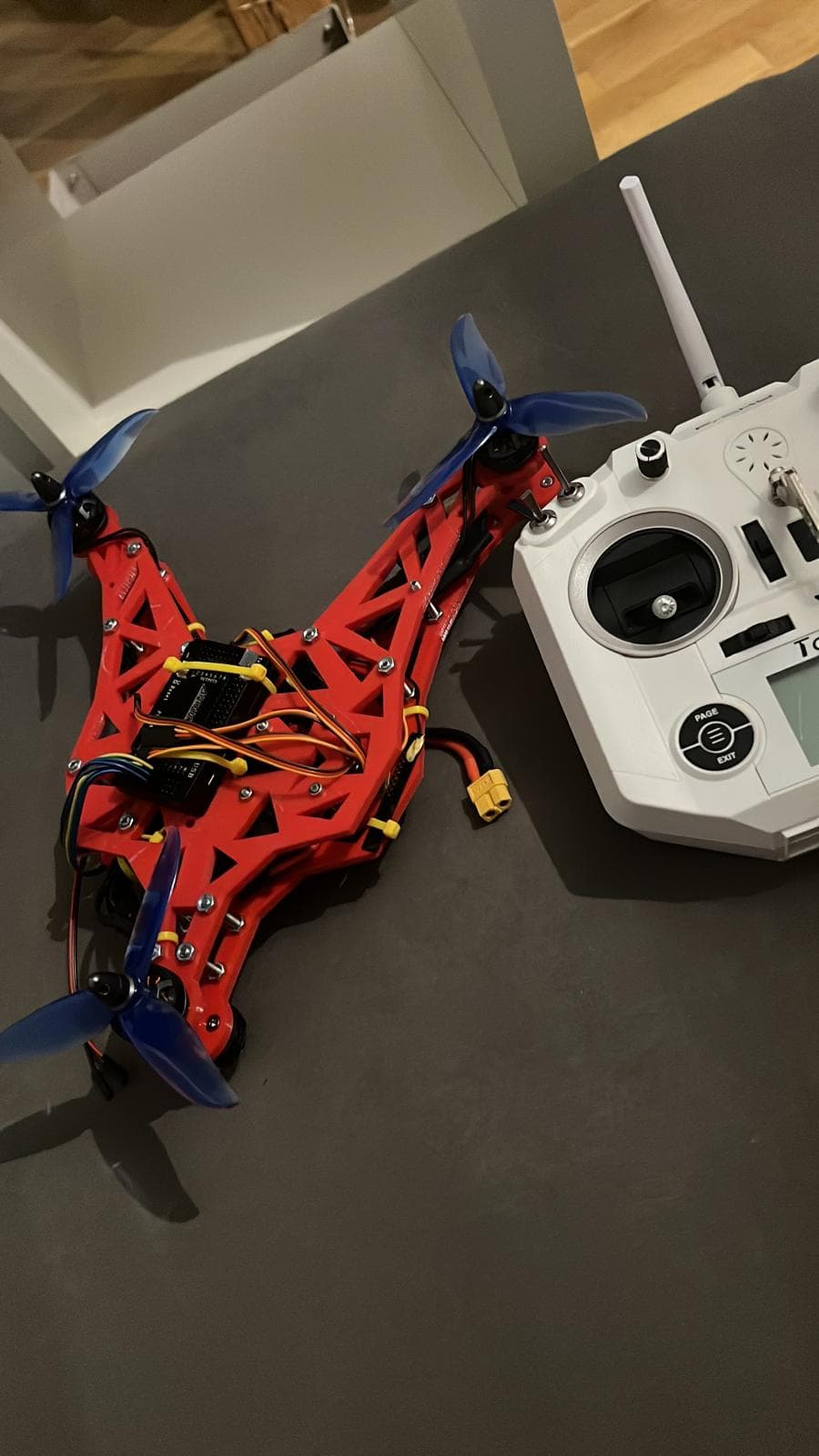
A 3D-printed Y4 multirotor: tricopter geometry with a coaxial rear motor pair instead of a yaw servo. Custom motor mixer, thrust-stand-derived yaw linearisation, and a deliberate motor-out flight test — Ardupilot-based flight control throughout.
Three arms, four motors, no yaw servo
After the first quadrotor build proved that a self-assembled multirotor could fly reliably, the obvious next step was not a better quad — it was a configuration that flies differently. The tricopter had always been the most appealing layout: three slim arms, a clean unobstructed view forward, and a shape that actually looks like an aircraft rather than a table. But the classic tricopter buys its yaw control with a servo that tilts the whole rear motor, and that servo is the configuration's Achilles heel — a mechanically loaded, constantly working part sitting in the propwash, and a single point of failure with no aerodynamic backup.
The Y4 is the answer to exactly that problem: keep the tricopter's three-armed geometry, but replace the tilting rear motor with a fixed coaxial pair — one motor on top of the rear arm, one hanging underneath, spinning in opposite directions. Yaw control comes from splitting torque between those two rear motors instead of from a servo. Four motors, four ESCs, zero moving parts beyond the rotors themselves — quad-style simplicity in a tricopter's body.
The catch, and the reason this became a project rather than a weekend build: a Y4 is aerodynamically and control-theoretically not a quad. The rear pair carries half the aircraft's weight, the lower rotor lives in the upper one's slipstream, and the yaw, pitch and thrust axes couple in ways a symmetric quad never shows. This page documents the build — and above all the flight-control work needed to make the configuration behave.
A 3D-printed truss frame in red PETG
The frame was designed in Fusion 360 and printed in red PETG: three arms built as open truss structures rather than solid beams, bolted to a twin-plate centre section that sandwiches the electronics. The truss pattern came out of a simple observation from the previous build — solid printed arms are heavy where they don't need strength and floppy where they do. Triangulated webs put the material where the bending loads actually run and cut arm mass by roughly a third at equal stiffness.
The rear arm is the special one: it carries a motor mount on both faces, top and bottom, with the lower motor hanging inverted. Both rear mounts are printed into the truss rather than bolted on, so the torque of the coax pair feeds directly into the web. The front arms take standard 2306-size motors with 7×4 three-blade propellers; the whole aircraft comes in at 940 g ready to fly with a 4S 3300 mAh pack.
Everything is deliberately serviceable: each arm is a separate print that bolts to the centre plates, so a crashed arm is a 4-hour reprint and four screws, not a new frame. Over the flight-test campaign that policy paid for itself twice.
Where does the centre of gravity go when one arm lifts double?
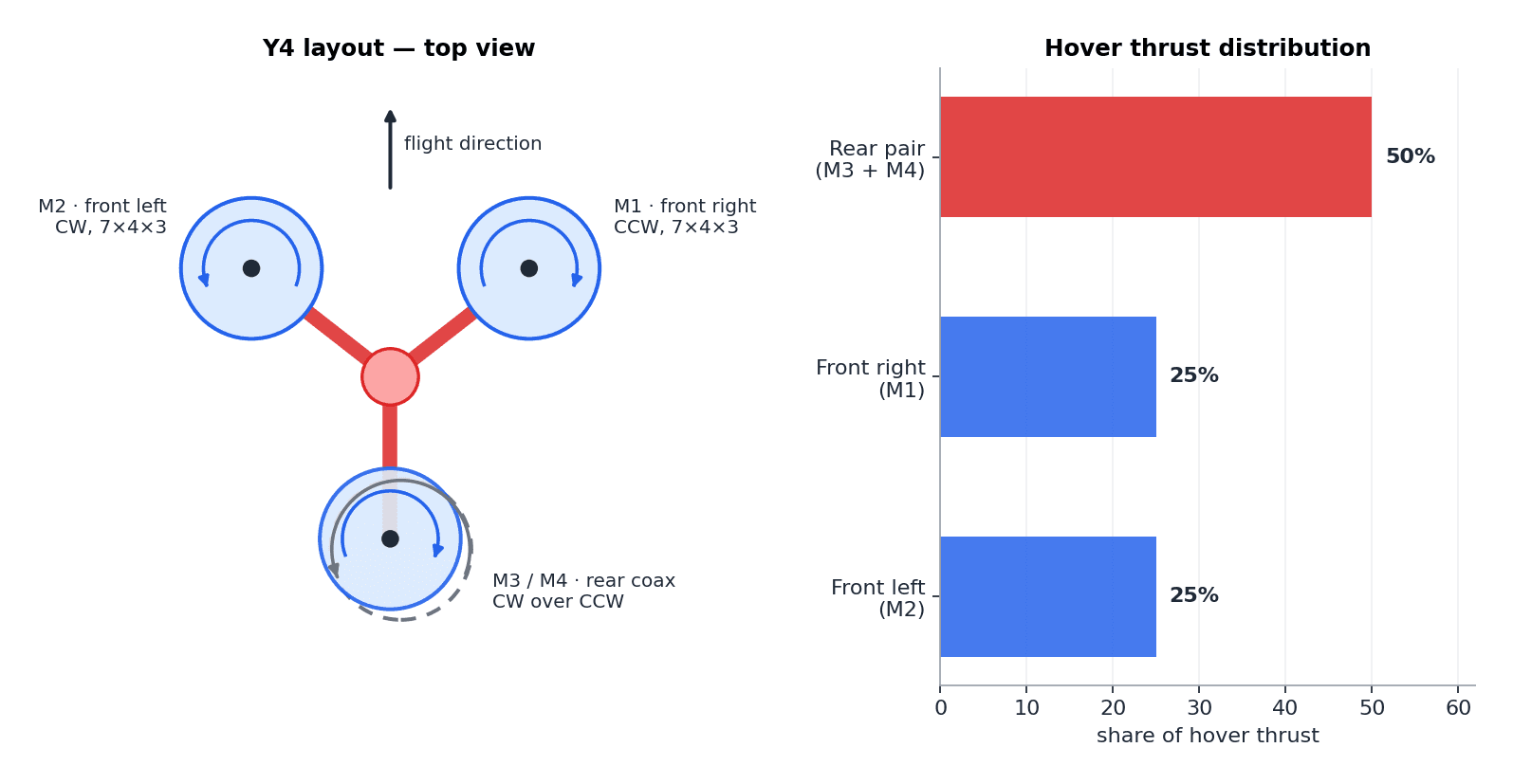
On a quad, balance is trivial: four equal rotors on a symmetric cross, CG in the middle, done. A Y4 breaks that symmetry in plan view. The rear station carries two motors, so in hover it produces half the total thrust while each front arm produces a quarter — and the aircraft only hovers level if the CG sits exactly at the centroid of that 25 / 25 / 50 thrust distribution, which lies noticeably further aft than the geometric centre of the three arms.
That number drove the whole packaging. Battery, flight controller and ESC wiring were arranged so the loaded CG lands on the thrust centroid with the standard pack, and the battery tray got 30 mm of fore-aft adjustment to compensate for different packs. Getting this wrong doesn't just cost trim: any static pitch moment has to be held by a permanent thrust split between front and rear, which eats control headroom and burns power continuously.
The plan-view layout also sets the control gearing. The front motors sit wide of the roll axis and do all the roll work; the rear pair sits on the centreline and contributes none. Pitch is the opposite — the rear pair has the longest lever arm. The mixer in chapter 05 is really just this drawing turned into numbers.
Measuring the price of stacking rotors
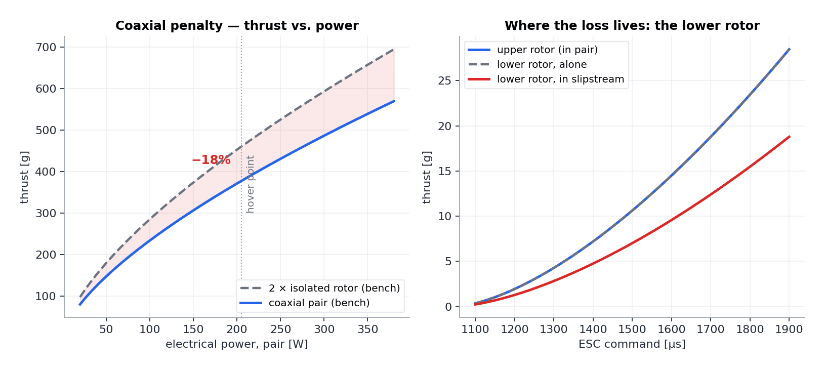
A coaxial pair is not two rotors — it's one and a half. The lower rotor works in the accelerated, swirling slipstream of the upper one: it sees higher inflow velocity, so at the same RPM it produces markedly less thrust. Before trusting the configuration in the air, the rear pair went onto a simple load-cell thrust stand to put numbers on the penalty.
The result matched the textbook surprisingly well: at the hover operating point the pair delivers about 18% less thrust than two isolated rotors at the same electrical power. Sweeping the motors individually shows where the loss lives — the upper rotor performs essentially as if it were alone, while the lower rotor gives up roughly a third of its isolated thrust once the upper one is spinning above it.
Two practical consequences fell out of the bench data. First, hover efficiency: since the penalty applies to half the aircraft's thrust, the Y4 pays roughly 9% more hover power than an equivalent quad — the measured hover draw is about 25 A on 4S, for just under seven minutes of flight on the 3300 mAh pack. Second, and more important for control: the pair's thrust is not a linear function of the two motor commands, and that nonlinearity is precisely what later showed up as a flight-control problem in chapter 10.
Turning the geometry into a motor matrix
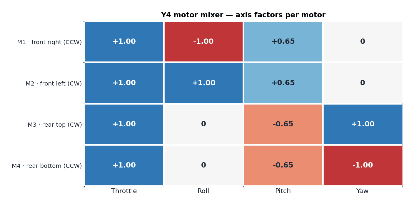
A multirotor flight controller reduces to one small piece of linear algebra: the mixer, which maps the four axis demands — throttle, roll, pitch, yaw — onto individual motor outputs. For a quad X the matrix is famous and symmetric. For the Y4 it has real character, and writing it down is the cleanest way to understand how this aircraft flies.
Roll lives entirely on the front motors: they sit wide of the roll axis while the rear pair is on the centreline with a factor of zero. Pitch is shared, with the rear pair pushing against both front motors across its long lever arm. Yaw belongs exclusively to the rear pair: the two coax motors carry equal and opposite yaw factors, so a yaw demand splits their RPM — one speeds up, one slows down — producing a net reaction torque while (ideally) leaving the pair's total thrust unchanged. The front motors, counter-rotating and symmetric, carry no yaw factor at all.
ArduCopter supports the Y4 as a frame type out of the box, but the default factors assume an idealised geometry. The factors were recomputed from the actual arm lengths and motor positions of this frame and set up as a custom motor matrix — the numbers in the figure are the ones that flew. The elegance of the arrangement is the decoupling on paper: roll commands don't touch the rear pair, yaw commands don't touch the front motors. How well that ideal survives contact with coax aerodynamics is the story of the tuning chapters.
The configuration's party trick: torque-split yaw
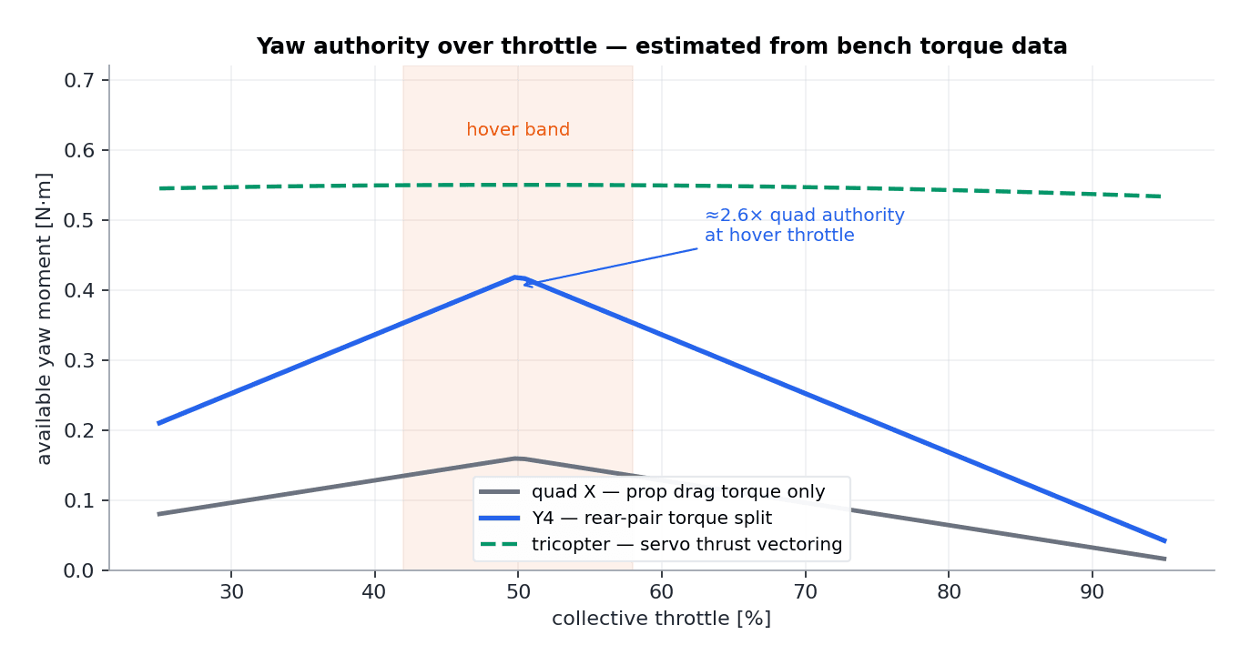
Yaw is the weakest axis of every flat multirotor. A quad can only yaw with the difference in propeller drag torque between its CW and CCW rotors — a small moment that arrives slowly, because the motors first have to change RPM against the propellers' inertia. The tricopter solves this with brute force by tilting a motor, vectoring real thrust sideways at the cost of the servo.
The Y4's rear pair is a third mechanism, and it's a genuinely good one. Because the two rear motors sit on the same axis and spin in opposite directions, splitting RPM between them produces a pure reaction torque about the yaw axis — with no net roll or pitch moment and, to first order, no net thrust change. And since the split can use the full command range of two motors that each carry a quarter of the aircraft's weight, the available moment is large: from the bench torque data, roughly 2.6 times what an equivalent quad can generate at hover throttle.
In the air this is the configuration's defining sensation. Yaw response is immediate and crisp in a way no quad of this size manages — the aircraft snaps its nose around like a tricopter but without a servo arm flexing anywhere. The flip side: all of that authority funnels through exactly two motors on one arm, which concentrates both the thermal load and, as the next chapters show, the coupling problems in one place.
ArduCopter, four ESCs and a Taranis
The flight controller is an F405-class board running ArduCopter, soft-mounted on the lower centre plate with the IMU as close to the CG as the packaging allowed. Four 30 A BLHeli_S ESCs drive the motors — the rear pair's ESCs were placed directly in the propwash on the rear arm for cooling, since chapter 06's torque-split yaw works those two hardest. Power comes from the 4S pack through an XT60 and a current-sensing power module, so every flight log carries voltage and current for the efficiency bookkeeping in chapter 04.
The radio link is a FrSky setup: Taranis Q X7 on the bench in the build photo, talking to an R-XSR receiver over SBUS, with telemetry carrying battery state and flight mode back to the transmitter. Channel 5 selects between Stabilize, AltHold and Loiter; a dedicated switch arms the motor-failure test logic used in chapter 11 — a deliberate decision that no experiment should ever be more than one switch away from a normal flight mode.
Compass and IMU calibration followed the same routine as the first quad build, with one Y4-specific addition: the ESC calibration and motor-order check matter more than usual, because swapping the two rear motors doesn't just mirror a control direction — it silently inverts the yaw axis while everything else looks correct in a bench test.
A printed frame meets a gyro: the 83 Hz problem
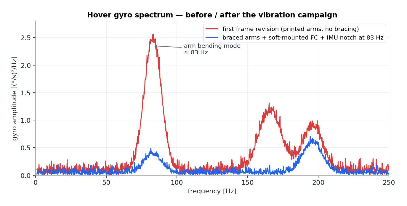
The first hover logs looked wrong before the aircraft had flown a full battery: the gyro spectrum showed a sharp resonance at 83 Hz, right in the band the rate controllers care about, plus propeller-order peaks further up. The 83 Hz line turned out to be the first bending mode of the printed front arms — a truss is stiff for its weight, but PETG is not carbon, and the mode sat low enough to be excited by normal motor operation.
The fix came in three layers. Structurally, a diagonal brace was added to each front arm's truss (a one-evening reprint, thanks to the modular arms), pushing the mode up and its amplitude down by a factor of about seven. Mechanically, the flight controller went onto softer standoffs, adding isolation above ~60 Hz. And in software, ArduCopter's gyro notch filter was parked on the residual peak so the rate loops never see what's left of it.
The lesson carried over to every printed aircraft since: log a hover, look at the spectrum, and treat the frame's modes as design parameters — before tuning any control loop. Rate-loop gains tuned on top of a resonance aren't tuning the aircraft, they're tuning the vibration.
First hover and the step-response campaign
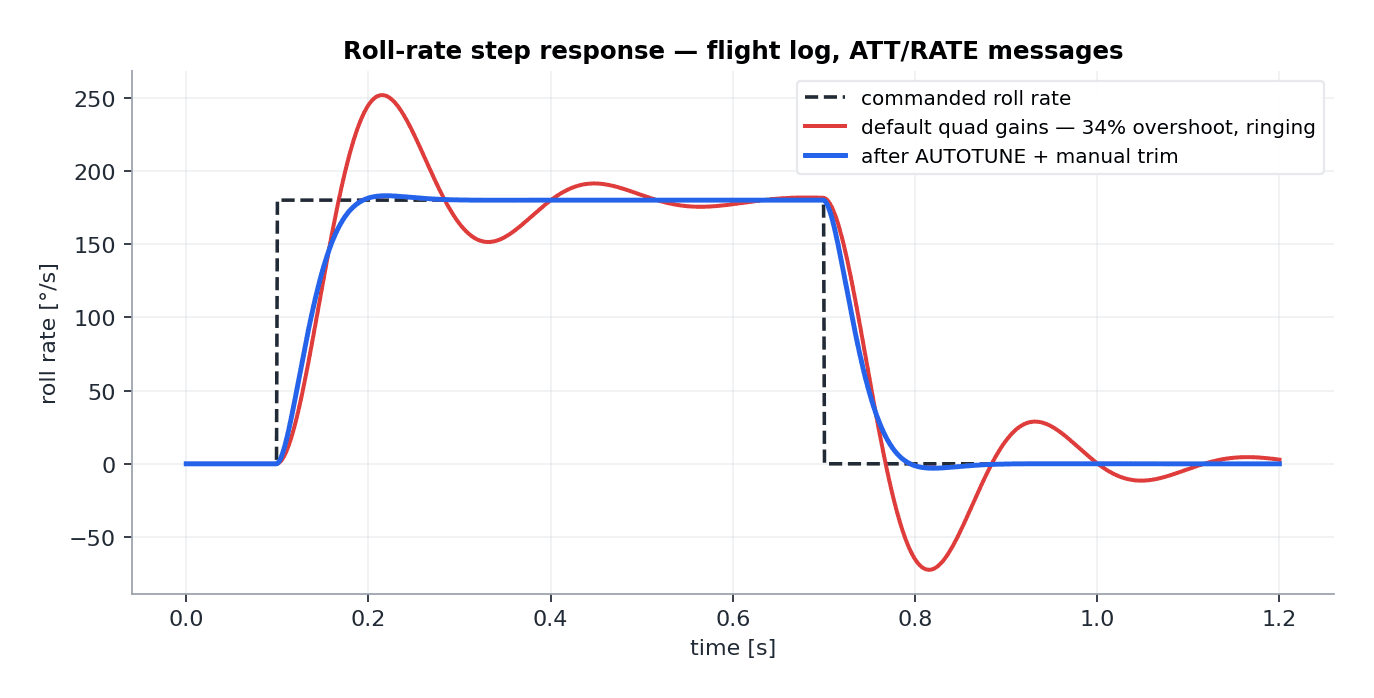
First hover happened on default quad-X gains, on the theory that they'd be wrong but not dangerous — which is exactly how it played out. The aircraft was flyable but nervous: roll in particular overshot visibly, because on a Y4 the roll axis is worked by only two motors instead of four, so the same rate-controller gain meets barely half the control effectiveness and a different axis inertia.
Tuning followed the classic log-driven loop: fly a set of sharp rate steps on each axis, land, and read the RATE messages. The initial roll response showed ~34% overshoot with visible ringing. An AUTOTUNE session got the gains into the right neighbourhood, and manual refinement — a touch more D, slightly reduced P on roll, feedforward brought up until the response leads the command — produced the final behaviour: crisp tracking with minimal overshoot on roll and pitch.
Yaw needed the opposite correction of every quad I'd tuned before. With 2.6× the usual authority, the default yaw gains were violently strong — the first yaw step nearly twisted the aircraft past its commanded heading with the rate limiter saturated. Yaw P came down by almost half, and the yaw rate limit went up instead: the configuration doesn't need aggressive gains to yaw hard, it needs permission.
Why every yaw input made the nose dip
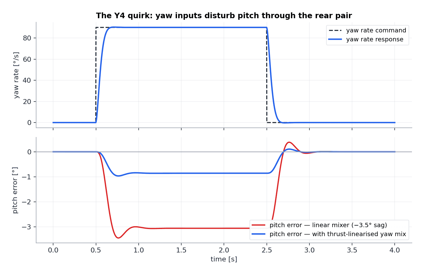
With the axes individually tuned, one behaviour refused to disappear: every brisk yaw input produced a small but repeatable nose-down pitch, about 3.5° at full yaw rate, which the pitch loop then had to claw back. On a quad this would indicate a mixer error. Here the mixer was correct — the physics was the culprit, and the thrust-stand data from chapter 04 already contained the explanation.
The mixer assumes the rear pair's total thrust stays constant during a yaw split: one motor up, one motor down, sum unchanged. But the pair's thrust is nonlinear in its individual commands — the lower rotor, already handicapped by the slipstream, loses more thrust when slowed than the upper one gains when sped up (and vice versa, asymmetrically). Every yaw split therefore changes the rear station's net thrust, and a thrust error on the arm with the longest pitch lever shows up immediately as a pitch moment. The decoupling that looked so clean in chapter 05's matrix dies in the coax aerodynamics.
The fix was to stop pretending the pair is linear. Using the bench thrust curves, the yaw split was reshaped into an asymmetric pair of command increments — the slowed motor is slowed less than the sped-up motor is accelerated, by exactly the amount that keeps the pair's predicted net thrust constant. Implemented as a thrust-linearised yaw mix on top of the standard matrix, it cut the pitch disturbance from 3.5° to under a degree, and the remaining error is well within what the pitch loop absorbs invisibly. This single fix changed the aircraft's character more than the entire gain tune.
Testing the redundancy claim the honest way
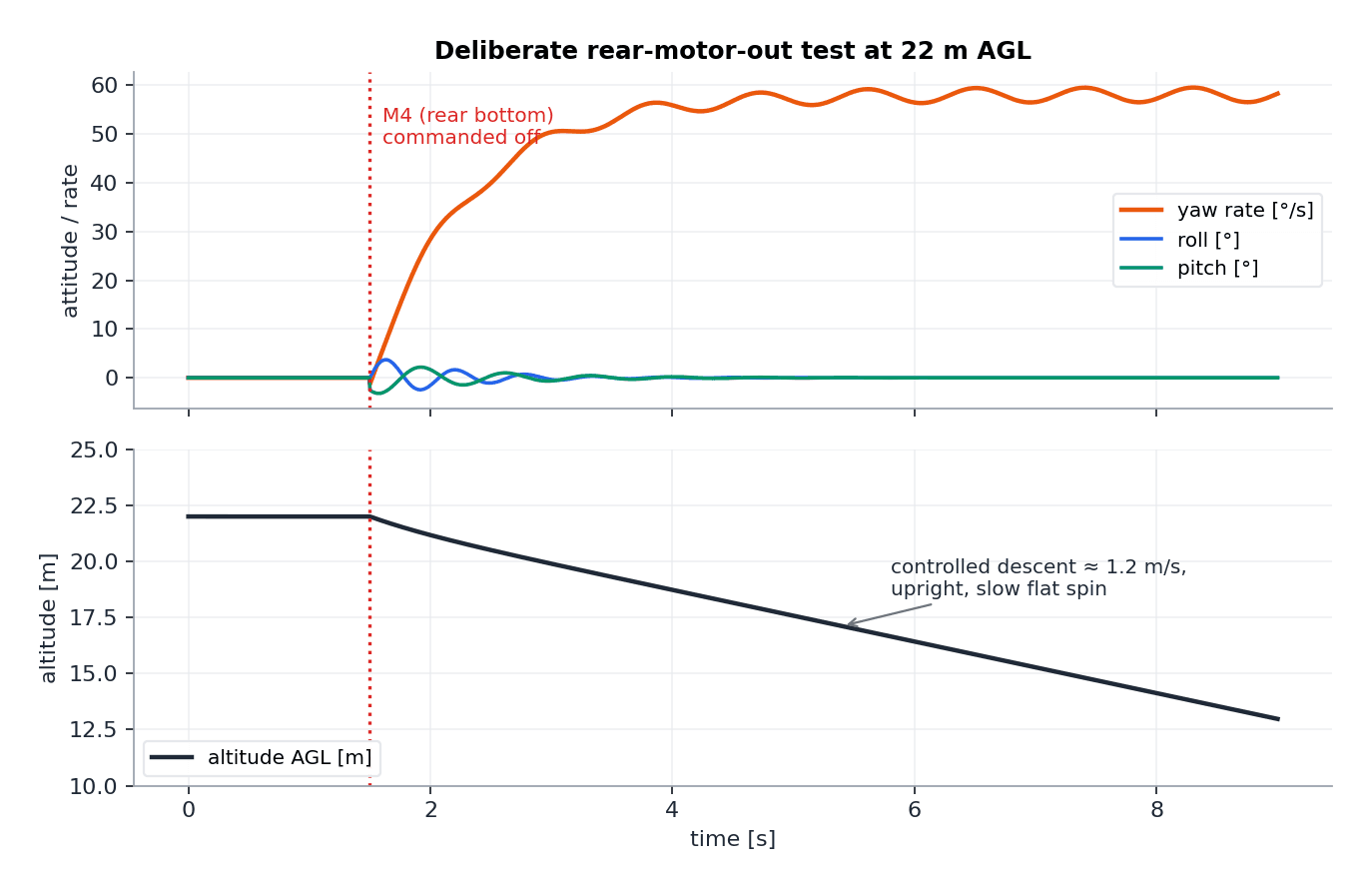
Half the argument for a coax rear was redundancy: lose one rear motor and the other still holds the rear of the aircraft up. That claim is worthless untested, so it was tested — deliberately, over grass, from 22 m: a switch on the Taranis commands the rear bottom motor to zero mid-hover while the logs record what the controller does with the remaining three.
The result validated the configuration with one honest caveat. Attitude never left a ±5° band: the surviving rear motor spooled up to cover the missing thrust, and roll and pitch stayed fully controlled throughout. What is lost is yaw — with only one rear motor there is no torque split, and its unopposed reaction torque puts the aircraft into a slow flat spin that settles near 60°/s, beyond what the front motors' zero yaw factors can counter. The aircraft can't hold heading, but it descends upright and on-position at about 1.2 m/s, spinning gently, to a landing that required nothing but a level throttle.
That is exactly the failure mode a Y4 promises: a broken rear motor turns a crash into a rotating but controlled descent. The same event on the tricopter this configuration replaces — a failed yaw servo, let alone a failed rear motor — has no comparable happy ending.
What the Y4 taught that a fourth quad never would have
As an aircraft, the Y4 ended up genuinely likeable: tricopter agility in yaw, quad simplicity in maintenance, and a demonstrated ability to survive its most likely motor failure upright. The costs are equally clear and equally measured — about 9% more hover power than an equivalent quad for the coax penalty, roll authority from only two motors, and a rear arm that concentrates the aircraft's hardest-working hardware in one place.
As a flight-control education, it was worth more than the previous builds combined. A symmetric quad hides the machinery: the mixer is trivial, the axes decouple by symmetry, and default gains mostly fly. The Y4 forced every layer into the open — control allocation from actual geometry, actuator nonlinearity breaking a clean mixer, structural modes contaminating rate loops, and a failure test designed on purpose instead of experienced by accident. Every one of those lessons transferred directly to the tilt-rotor VTOL project that followed, where control allocation stops being a matrix and becomes a function of tilt angle.
The airframe still flies. The rear ESCs have been replaced once, the front arms twice, and the yaw response still makes every quad feel lazy.