
EPFL Spacecraft Team
Structures pole — mass model, test stand design & vibration testing for the CHESS satellite
- Role
- Structures pole — FE model, dummy masses, fixture, instrumentation
- Duration
- 5 months (02.2025 – 08.2025)
- Team
- Structures pole of the EPFL Spacecraft Team
- Tools
- CAD, Finite Element Analysis, Shaker / accelerometry, Machine shop
Building a mass model of the CHESS satellite for vibration qualification
This was a single, focused project done during my exchange semester at EPFL (Feb–Aug 2025) — five months on the EPFL Spacecraft Team's structures pole. That timeframe is the whole reason the scope was what it was: get one clear deliverable done end to end rather than follow a subsystem across years.
The deliverable was a mass model of the CHESS satellite — a structural stand-in that reproduces the real spacecraft's mass, centre of gravity and stiffness distribution without any of the functional (and expensive, flight-critical) electronics. A mass model lets you take the structure to a shaker table and qualify it against launch vibration long before you would ever risk flight hardware.
My task had two halves that had to end up describing the same object: a digital model to simulate, and a physical model to actually put on the shaker — then compare the two.
Starting from a satellite that was almost finished
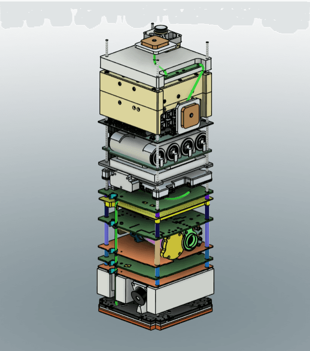
CHESS is a student-built cubesat with a tall, stacked internal architecture — subsystem trays, avionics boards and a payload threaded onto a slender aluminium primary structure. By the time I joined, that design was essentially frozen, which is exactly the point at which a mass model becomes worth building: the geometry and the mass budget are stable enough to reproduce faithfully.
So the flight CAD became my master reference. Every tray position, every board mass, every mounting interface and the overall centre of gravity had to be read off this model and then rebuilt in a way that behaves structurally like the real thing — without being the real thing.
Qualify the structure, not the electronics
A satellite has to survive the vibration of launch before it ever has to survive space. You want to prove the primary structure and its joints can take qualification-level loads — but you do not want to strap a fully populated flight unit to a shaker to find out.
The mass model resolves that: it matches the flight satellite where it matters for a structural test — total mass, centre of gravity, and the way mass is distributed and mounted along the structure — while replacing every functional board with an inert dummy of the same mass and footprint. If the structure and the model agree, the shaker campaign is meaningful and nothing irreplaceable is ever at risk.
A finite-element model to predict how it rings
The first half was digital. I built a finite-element model of the mass model: the aluminium frame as its structural members, each dummy board as a lumped mass at the right location, and the bolted interfaces represented so the load path through the stack was captured.
The output that matters here is a modal analysis — the natural frequencies and mode shapes of the assembly. Those first modes are what a vibration test hunts for, and having them predicted up front tells you where to expect resonances, whether the structure clears the launcher's minimum-frequency requirement, and where to place the accelerometers on the real hardware.
Metal plates and weights standing in for every board
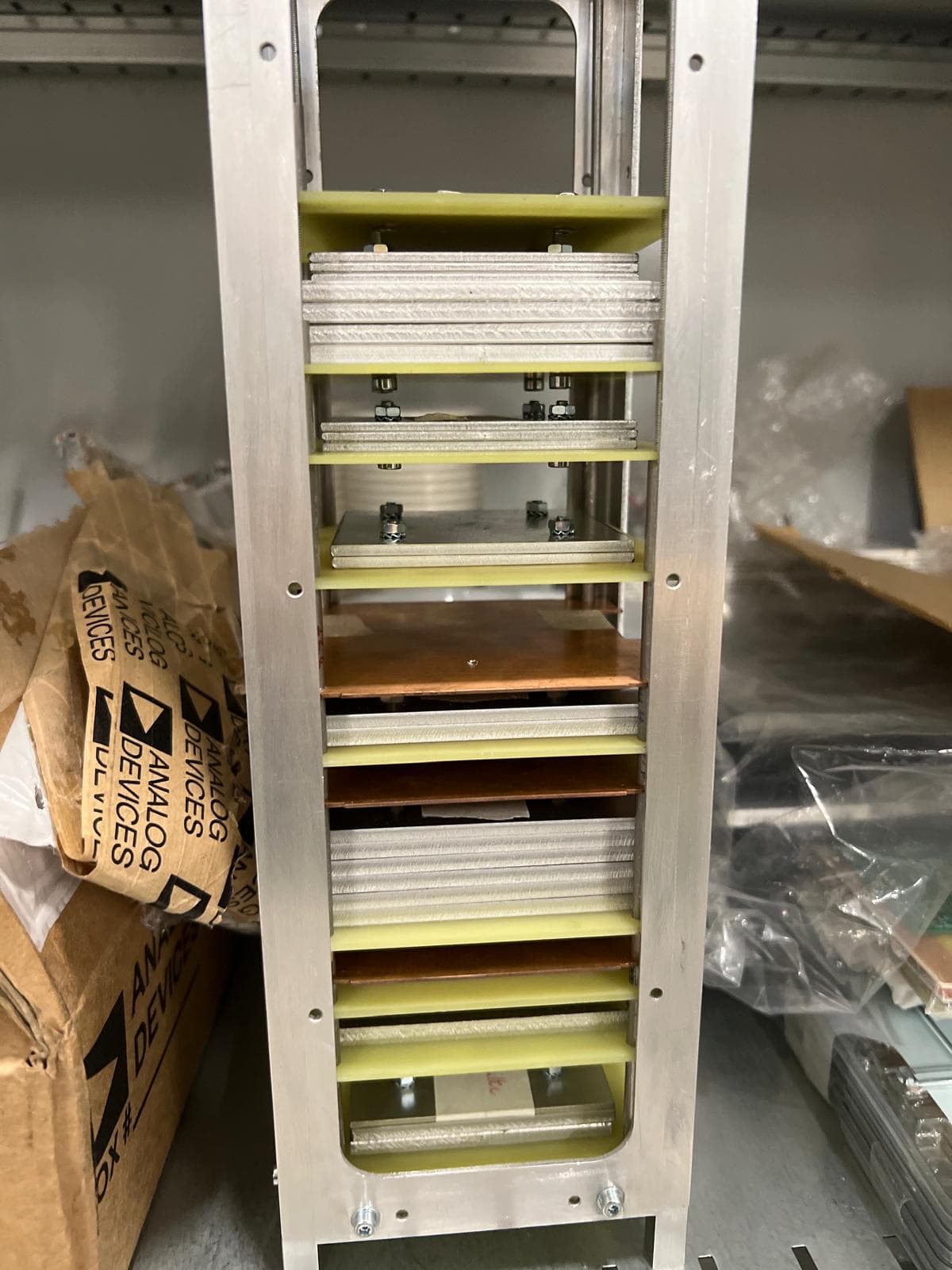
With the model predicting behaviour, the physical build had to reproduce it. Each real PCB and subsystem tray was replaced by a dummy: metal plates and added weights machined to match the mass and mounting footprint of the component they stood in for, stacked with the same G10 spacers and threaded rods as the flight boards.
The goal was ruthless similarity to the original — same masses in the same places, same stack order, same interfaces — so that the physical object and the digital object are genuinely two descriptions of one satellite, and a shaker result on one says something true about the other.
Turning the CAD into aluminium in the EPFL workshop
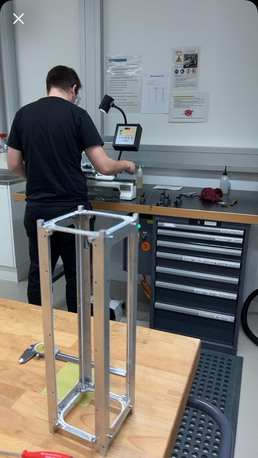
The primary structure and the dummy masses were then manufactured in the EPFL student workshop — turning, milling and drilling parts to match the CAD dimensions and the interface holes that let the stack bolt together the same way the flight structure does.
This is the part of the job I like most: a plan meeting a workshop and occasionally turning out to be wrong in an interesting way. Getting the frame square, the hole patterns aligned and the tolerances tight enough that the assembly actually behaves like the model is where a mass model is made or lost.
Stacking the model so it matches the simulation
Assembly is where the two halves are reconciled. The dummy trays and plates go onto the rails in the flight stack order, the threaded rods are torqued to spec, and the whole column is checked so its total mass, centre of gravity and stiffness distribution line up with what the finite-element model assumed.
The result is the physical twin of the digital model: an inert, metal-and-G10 version of CHESS that is ready to be shaken.
Fixturing and instrumenting the model for test
A shaker test is only as good as the thing bolted between the table and the article, so the test stand was its own design job. The fixture has to reproduce the satellite's launch interface exactly — same bolt pattern, same clamping — while being stiff enough that its own resonances sit well above the frequency band of interest. A fixture that flexes inside the test band contaminates every measurement taken through it: you can no longer tell whether a peak belongs to the satellite or to the adapter holding it.
It also has to work in three orientations, because the model is qualified along each of its axes in turn, which means either a fixture that can be reconfigured or one rigid enough to be re-mounted without changing what it contributes.
Instrumentation was planned off the back of the finite-element results rather than by eye. Accelerometers went at the base, to measure what the shaker was actually delivering into the structure, and at points up the stack chosen where the predicted mode shapes have their largest deflections — because an accelerometer sitting at a node of a mode will not see that mode at all, however well it is glued down.
The campaign itself follows the standard qualification sequence: low-level sine sweeps to locate the resonances, then random vibration to qualification levels along each axis, with the sweeps repeated in between.
A low-level sine sweep to find the first modes
The campaign opens with a low-level sine sweep — a gentle sweep across the frequency band that excites the structure just enough to reveal where its resonances sit, without overstressing anything. This is the physical measurement of the same first modes the finite-element model predicted.
That first sweep is also the reference signature: it gets repeated after every high-level run, because a resonance that has shifted between two sweeps is the classic tell-tale of something loosening or cracking inside the stack.
Random vibration to launch loads on each axis
With the resonances located, the model is driven with random vibration representative of the launch environment, at qualification levels, along each of its three axes. Between the high-level runs the low-level sine sweep is repeated, and the before/after resonance signatures are compared to confirm the structure came through undamaged.
For a mass model the pass criterion is really about the structure and its joints: it should ride out the qualification spectrum with its modes unchanged and its bolted interfaces intact.
Closing the loop between the model and the measurement
The final step is correlation: line the measured natural frequencies up against the finite-element prediction and tune the model — bolt stiffnesses, joint representations, boundary conditions — until the digital and the physical agree. Where they disagree is where the modelling assumptions were wrong, and joints are almost always the culprit, because a bolted interface is the one thing a finite-element model cannot represent from first principles. Its stiffness depends on preload, surface finish and how the parts actually seat, and it is fitted from test data rather than derived.
My five months covered building both the digital and the physical model, designing the fixture, and getting the assembly instrumented and onto the shaker. I handed the campaign over at the correlation stage, and the team carried the final model-tuning forward from there — so the measured-versus-predicted frequencies are their result to report, not mine.
Stopping there is worth being explicit about. The value of what I built is not a correlation number I can quote; it is that the model and the hardware were made to describe the same object closely enough that the comparison would be meaningful when it was made.
One satellite, described twice, ready to trust
In five months the project went from a near-frozen flight design to two matched descriptions of the same satellite — a finite-element model that predicts how CHESS rings, and a machined, assembled mass model ready to be shaken — plus the fixture, instrumentation plan and test procedure the team can reuse when the real structure's turn comes.
It is a compact, complete slice of structural engineering: read a design, predict its behaviour, build the hardware, test it against launch loads, and compare reality back to the model.